3D circuit modeling and Factory Acceptance Testing (FAT) exist to find structural conflict, access constraint, and design discrepancy before equipment ships to the site — when problems are still cheap to solve. A problem found in the model costs engineering hours. The same problem found during installation costs weeks and significant additional expense.
Which Types of Projects Benefit From 3D Modelling and Factory Acceptance Testing?
All three project types that AMPCO Minerals delivers, new circuits, equipment and structural replacement, and capacity expansion, go through the 3D modeling and Factory Acceptance Testing process.
- New circuits: the full plant is modeled as a complete system before fabrication begins, surfacing structural conflicts, access constraints, and material transfer point issues before a single component is built.
- Equipment and structural replacement: new equipment is modeled against the dimensions and interfaces of the existing circuit it will connect to, verifying that structural connections, maintenance corridors, and material transfer points will integrate cleanly before anything is fabricated.
- Capacity expansion: additional equipment and structures are modeled within the existing circuit layout, confirming that new and existing infrastructure work together as a single system and that installation can proceed without disrupting running production.
For replacement and expansion projects, this step is especially critical: it is the point where the engineering intent meets the physical reality of what is already on site, and where conflicts are resolved within AMPCO Minerals’ engineering environment rather than under production pressure in the field.
Why Is There a Window in Every Project When the Cost of Finding a Problem Is Close to Zero?
There is a moment in every mineral processing project — somewhere between finalizing the circuit design and shipping the first piece of equipment — when the cost of finding a problem is close to zero.
That window doesn’t last long. Once fabrication begins, changes carry a price. Once equipment ships, that price rises sharply. Once the plant is in the ground and the first material runs through it, you’re no longer solving a design problem, you’re solving an operational one, under production pressure, with real consequences for every day the circuit doesn’t perform.
The goal of 3D circuit modeling and Factory Acceptance Testing is simple: find the problem that can be found before it becomes the expensive kind.
Why Aren’t 2D Drawings Enough for a Mineral Processing Circuit?
Traditional 2D flowsheets and layout drawings are essential tools, they communicate the circuit design clearly and efficiently, and they remain the foundation of any engineering package. But they have a fundamental limitation: they represent the world as flat.
A mineral processing circuit is not flat. It occupies three-dimensional space, with equipment at different elevations, structures intersecting at multiple levels, access points that need to accommodate people and machinery, and material transfer points that need to handle the actual physics of bulk material flow.
On a 2D drawing, a structural member and a conveyor drive can occupy the same space without anyone noticing. On a 3D model, that conflict is impossible to miss. This isn’t a hypothetical concern — it’s the category of problem that shows up during installation, when the crane is on-site, the schedule is committed, and the cost of the fix has multiplied by an order of magnitude.
What Does a 3D Circuit Model Actually Reveal?
Building a 3D model of the complete circuit, not individual pieces of equipment in isolation, but the full system as it will be installed, surfaces issues that would otherwise only be discovered on-site.
Structural Conflicts and Access Constraints
Equipment that can’t be maintained without removing adjacent structures. Walkways that don’t connect. Platforms that don’t have enough clearance for the maintenance crew to work. Every one of these issues is straightforward to resolve in a model, none are straightforward to resolve in the field.
For replacement projects, the model also validates that new structural connections align with existing foundations and steelwork, confirming compatibility before fabrication, not during installation.
Material Transfer Points
The transitions between conveyors, feeders, crushers, and screens are among the highest-wear, highest-maintenance areas in any circuit. The 3D model allows these interfaces to be engineered rather than assumed.
Material transfer points, chute angles, impact zones, and containment geometry can all be evaluated and optimized before fabrication begins. For expansion projects, this includes the transfer points between new equipment and the existing circuit it feeds into or receives from.
Spillage and Dust Management
The geometry of material flow through each transition determines where buildup will occur, where spillage risk is highest, and where dust suppression needs to be designed in rather than added later. This can be assessed at every transfer point and discharge location in the circuit, before a single component is fabricated.
Installation Sequence Planning
Understanding how the circuit assembles, which pieces go in first, what access is required at each stage, where the physical constraints are during assembly, produces a more efficient installation with fewer surprises.
For replacement and expansion projects, installation sequence planning also addresses how new equipment is brought in and connected while the surrounding circuit continues to operate, minimizing disruption to production.
What Happens During Factory Acceptance Testing?
The 3D model addresses the geometry. Factory Acceptance Testing addresses the reality.
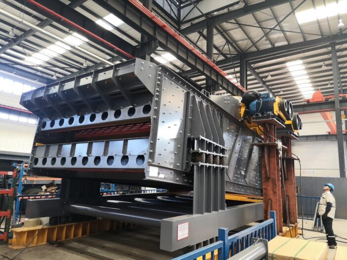
When all equipment for a circuit has been fabricated, we encourage our customers to visit the factory to review the trial assembly of various plant modules before it ships.
This is not a final inspection of individual pieces, it is a functional review of the circuit as an integrated system, the closest thing to a commissioning run that can be conducted before the equipment reaches your site.
Design Validation
Validation against project specifications and local standards confirms that what was designed is what was built, and that it meets the regulatory and contractual requirements of your project.
Discrepancies identified here are resolved in a controlled environment, and not during commissioning on-site.
Transitional Area Review
Attention focuses on the locations where spillage and accelerated wear are most likely, conveyor discharge points, chute transitions, crusher feed arrangements. Seeing these in three-dimensional reality consistently reveals details that benefit from adjustment.
Conveyor-to-Station Interface Evaluation
Alignment, clearances, hood geometry, and containment are verified against the actual fabricated equipment rather than nominal dimensions.
Access Point Confirmation
Where the 3D model establishes the design intent during engineering, the trial assembly confirms the physical reality — that personnel and machinery can safely reach all equipment during normal operation and maintenance.
HAZOP Study Support
A Hazard and Operability (HAZOP) study identifies potential safety and operability risks systematically. Conducting it during FAT, with the physical equipment present, allows the team to evaluate hazards in context rather than from drawings alone. Issues identified can be addressed before the circuit ships, when modifications are still straightforward.
What Does This Mean for Different Members of Your Project Team?
For customer operations teams, the FAT is an opportunity to understand how the circuit will operate before it arrives — to see the access points, the maintenance procedures, the material flow.
For maintenance engineers, it’s a chance to identify anything that will make the equipment harder to service than it needs to be. For project managers, it’s the point where schedule confidence is either earned or revealed to be optimistic.
At AMPCO Minerals, we consider the 3D modeling and FAT process a core part of what we deliver across all project types — new circuits, equipment replacement, and capacity expansion. It’s how we make sure the circuit we’ve engineered performs the way we designed it to from the first day of production.
Frequently Asked Questions
Does 3D circuit modeling apply to equipment replacement projects as well as new plants?
Yes. For equipment and structural replacement projects, the 3D model is built to include both the new equipment and the existing circuit it connects to.
This allows structural interfaces, maintenance access corridors, and material transfer points between new and existing equipment to be verified and resolved before fabrication — which is especially important when the surrounding circuit is still in operation and downtime for field corrections is costly.
How does 3D modeling help integrate new capacity into an existing circuit?
For capacity expansion projects, the 3D model confirms that new equipment and structures work together with the existing circuit as a single integrated system. Transfer points between new and existing equipment, structural connections, access routes, and installation sequences can all be resolved in the model.
The goal is to confirm that everything fits and functions before fabrication begins — so installation can proceed with minimal disruption to running production.
What types of problems are most commonly found during 3D circuit modeling?
The most common findings are structural conflicts (a steel member and a conveyor drive occupying the same space), access constraints (platforms that don’t provide adequate clearance for maintenance), and material transfer point geometry that would cause spillage or accelerated wear.
For replacement and expansion projects, mismatches between new equipment interfaces and existing structure dimensions are also frequently identified and resolved at this stage.
Who should attend Factory Acceptance Testing from the customer side?
Operations engineers, maintenance engineers, and project managers all benefit from attending FAT. Operations teams gain a working understanding of how the circuit will run. Maintenance engineers can flag anything that will complicate servicing.
Project managers can confirm the circuit meets specifications before it ships. The more of your team that participates, the more value the FAT delivers.
What is a HAZOP study, and why is it conducted during Factory Acceptance Testing?
A Hazard and Operability (HAZOP) study is a structured review that systematically identifies potential safety and operability risks in a process circuit.
Conducting it during FAT, with the physical equipment present, allows the team to evaluate hazards in context rather than from drawings alone. Issues identified can be addressed before the circuit ships, when modifications are still straightforward.
Learn more about how we guide projects from concept to mineral production on our Project Capabilities page.